


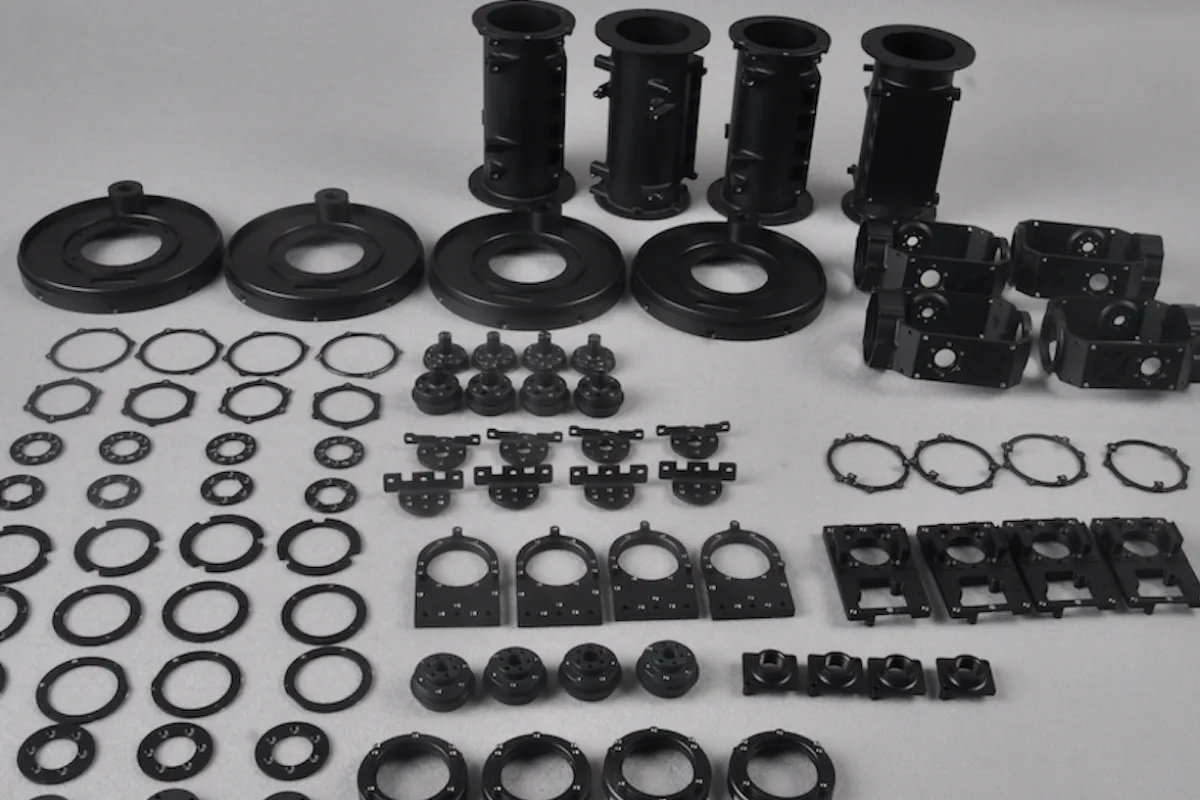
Optical systems depend on mechanical parts that keep lenses, sensors, apertures, and electronic modules in repeatable positions. A small shift in a mounting surface or hole pattern can change optical alignment and affect measurement or imaging. For brass CNC machining, the same principle applies to mounts, spacers, and threaded hardware: material, geometry, surface finish, and dimensional relationships must support stable assembly.
Optical Performance Relies on Stable Mechanical Positioning
When an optical mount is used to create a reference system for precision CNC parts, those parts need to be maintained in alignment throughout their use. For example, if one mounting surface is tilted, a hole (bore) is shifted, or a housing deforms while it is being assembled; then the optical axis will also be moved. Therefore, both the rigidity, flatness, perpendicularity, and positional accuracies of the parts are as important as the basic dimensioning tolerances.
The WayKen photoelectric module holder project demonstrates this problem. The aluminum 7075-T6 holder was 94.5 x 71 x 47mm in size with 10 surfaces to machine: a top, bottom and 8 sides. The drawing called for 0.02 mm control for flatness, parallelism, perpendicularity, circular runout and coaxiality.
This requirement was very much like the biomedical enclosure project which also created similar requirements. The AL6061-T6 shell enclosures had a perpendicularity tolerance of 0.03 mm, flatness of 0.02 mm, surface profile of 0.05 mm and dimensional tolerances of 0.03 mm for specific holes.
Mounting Surfaces and Hole Systems Control Component Alignment
Mounting surfaces establish contact, while hole systems determine the position of screws, brackets, sensors, and optical modules. Each interface should reference a functional datum. A hole can meet its diameter tolerance while still being incorrectly located relative to a datum. Functional inspection therefore needs to consider position, orientation, and relationships between features.
WayKen’s photoelectric holder used 3-axis plus 3+2-axis machining instead of continuous simultaneous 5-axis machining because its mostly planar cavity structure could meet requirements economically. Its 2.5 mm walls, with some areas only 1 mm thick, created deformation risk. WayKen machined the side structures first while material remained as reinforcement, then machined cavities using small cutting depths and feeds.
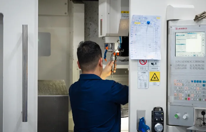
For custom machining service, this illustrates how machining sequences can protect alignment. Continuous 5-axis machining would have reduced clamping from three operations to two, but the selected 3+2 approach offered lower cost while meeting the 0.02 mm requirements.
The biomedical enclosure required another strategy because its irregular shapes needed multiple machining directions. WayKen used 5-axis CNC machining to reduce error accumulation between surfaces. Its in-machine inspection system used sensors and laser measurement to compare machining data with design requirements and detect deviations during production.
How WayKen Machines and Inspects Optical Mounting Components
Optical parts are sometimes finished to meet geometric tolerances as well as surface finish requirements. For example, in the Biomedical Enclosure Project, the black anodic treated parts were required to have a coating thickness of 0.003 – 0.012mm while specific surfaces needed to have a Ra of 1.6. WayKen employed high speed machining using carbide tooling and controlled machining allowance prior to anodizing, and then inspected both coating thickness and surface roughness after treatment.
The manufacturing logic is the same for brass CNC machining of all important features such as critical threads, bores, seats and mounting faces. Allowances are made according to material properties and finishing practices. The machining performance of brass may vary compared to the Aluminum Alloys that WayKen has demonstrated in their previous examples; therefore, it would be best to select your own tools based on the grade of the specified material rather than copying the tools and cut settings from other materials.
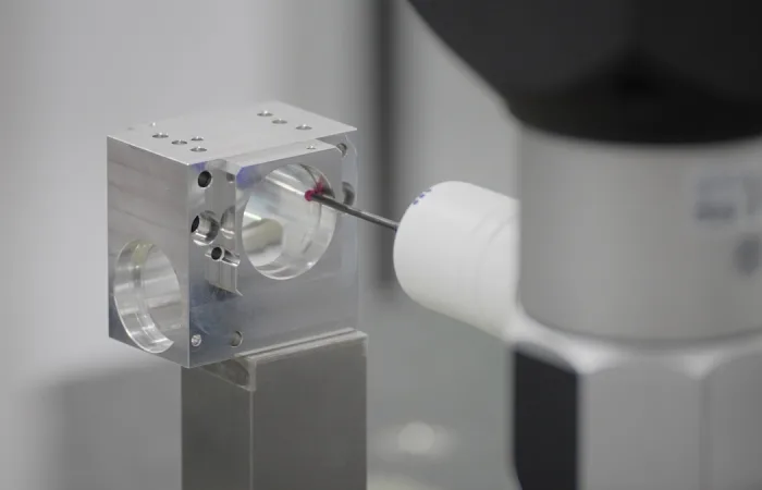
WayKen used a Zeiss CMM for the final inspection of the products to ensure that hole position and hole perpendicularity was verified through probing the area surrounding the hole to locate its center. This increases confidence in the assembly process. The photoelectric holder project also included first article inspection prior to beginning production. First article inspection allowed for definition of all key dimensions which supported sampling inspections throughout the remaining 50 piece production run.
Conclusion
Optical mounting components require stable geometry because mechanical alignment directly influences optical performance. Flatness, perpendicularity, hole position, coaxiality, surface finish, and coating thickness can all affect how components assemble and remain aligned. WayKen’s photoelectric holder and biomedical enclosure projects show how machining sequence, multi-axis processing, finishing control, and CMM or in-machine inspection address these relationships. When a custom machining service integrates these controls, CNC parts can maintain repeatable optical interfaces.