What are Scan Lines?
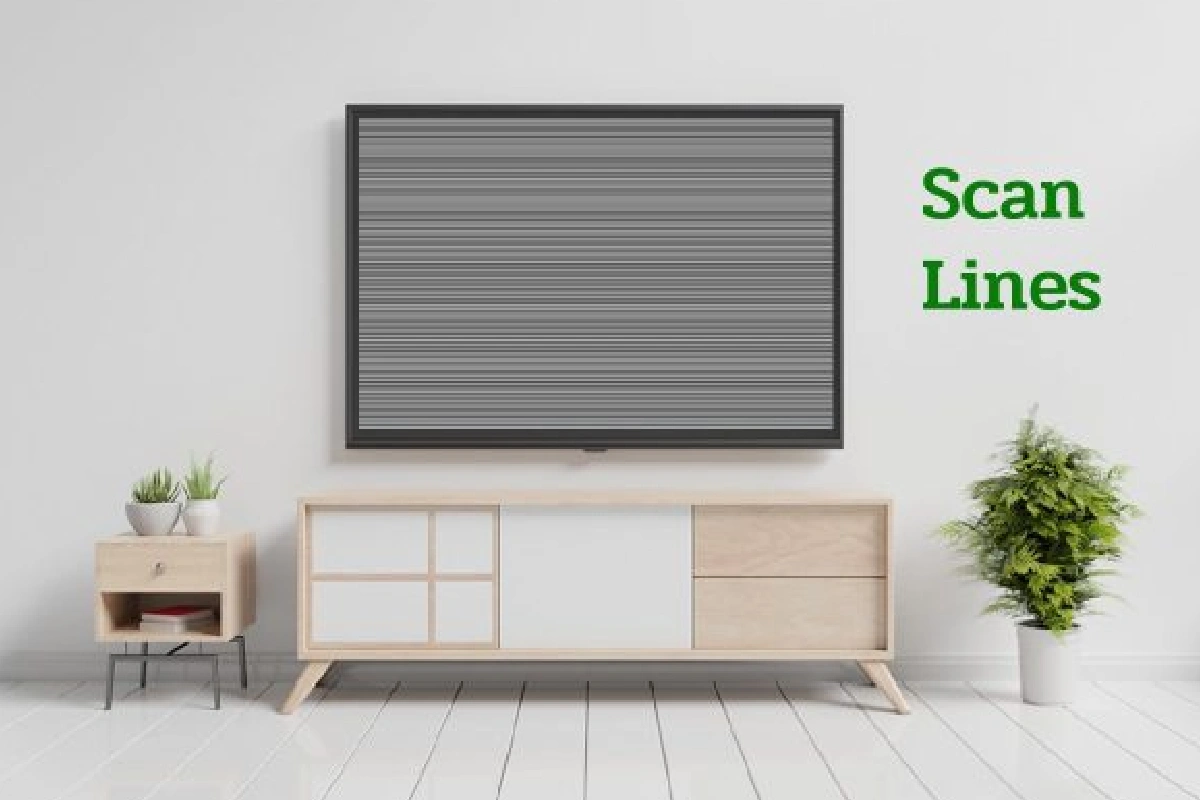
Scan lines generally refer to a line of vertical resolution, running across a screen horizontally, on a cathode ray tube (CRT) computer monitor or standard-definition television (SDTV) screen. Monitors and television screens using a CRT tube have a screen consisting of rows arranged horizontally across the screen, count vertically from top to bottom, and called vertical resolution. The images displayed on this type of screen creates by an “electron gun,” causing the photos to appear on every pixel on the screen, line by line. Each line displayed was called a scan line, although the process was generally too fast for human perception.
The basic way a CRT computer monitor works is through a tube that includes numerous pixels arranged in a series of horizontal lines across the screen. These lines count to determine the vertical resolution of the said screen; an SDTV generally has about 525 with 480 visible lines. Each of these lines as scan lines. The image on a screen created by the pixels in each line adequately illuminate by electrons moving from a filament, called an “electron gun,” on the back of the monitor or television onto the screen.
A scan lines mentions each line of pixels that light up from top to bottom and generally from left to right. This procedure is so fast that the human eye and brain often do not recognize the scans as individual processes. Each full scan of the screen on a progressive scan television or monitor generally occurs between 30 and 60 times per second. There are two ways to illuminate or scan each scan lines on a screen: interlaced and progressive scan.
Analysis of Scan Lines

First, we divide the top and bottom sides of the rectangle into a top side (that is, the side with a large y coordinate parallel to the x-axis) and a bottom side (the side with a small y-coordinate parallel to the x-axis) side). Then we sort the top and bottom sides of all the rectangles according to their coordinates and from small to large, and we can get 3 scan lines.
And because the above 2 rectangles have 4 different floating-point x coordinates, we need to discretize the x coordinate so that the line segment tree can hold the information.
As shown in the previous figure, 4 different x-coordinates divide the x-axis into effective intervals 3. Here we must pay attention to each leaf node (control interval [L, L]). It does not refer to the X coordinate [L ], but to the interval [X [L], X [L + 1]]. The interval [L, R] controlled by other nodes in the line segment tree also refers to the x coordinate axis. The interval range L to the interval Rth, the coordinate range X [L] to X [R + 1].
We then read each scan line in Y coordinate order from small to large, and we maintain that all scan lines that we currently read can effectively cover the maximum length of the X-axis sum. Here we need to pay special attention to whether we read the scan line is the bottom side of the rectangle. Then we make the range cnt bit +1. If it is the top side, then the range cnt is -1. So if cnt = 0, it means that the range controlled by the node not cover, While cnt! = 0, it means that several blocks owned by the node still cover.
First Scan Lines
We read the bottom edge of rectangle 1, then the area cnt is + 1 = 1, so the area [10, 20] is covere, and then all the area The length to cover is 10. So the height difference between the second scan line and the first scan lines is 5. So it doesn’t matter what rectangle or side the second scan line is or what range it can cover the x-axis, the blue rectangular area in my image should calculate the total area. The entire area rets + = sum [1] * (the height of scan line 2-the height of scan line 1). It is not like this)
Second Scan Lines
Since the second is also the bottom side, the cnt + 1 of [15,20] and [20,25] makes our coverage become [10,25] And the third scan line is at the height of 20, so this time we need to increase the area above the dark blue stripe = sum [1] * (the height of the scan line 3 – the size of the line scan 2).
Third Scan Lines
Because the third scan lines is the upper edge of the interval [10,20], the cnt of the corresponding interval must -1, so the cnt of the gap [10, 15] = 0 The cnt-1 in the hole [15,20] becomes 1. The cnt in [20,25] remains 1. No change, so the effective length of the x-axis currently covered is 10, which is the interval [15,25]. So the magnified area is the brown part in the image.
At this point, the sum of the area of the rectangles calculate, since for any rectangle, the bottom edge (cnt + 1) is read first and then the top edge (cnt-1), so in the update process from the line tree, any node The cnts are all> = 0.
Conclusion
Scan lines generally refer to a vertical line of the resolution, which crosses a screen horizontally, on a cathode ray tube (CRT) computer display or standard-definition television (SDTV) display. Monitors and television screens that rummage-sale a CRT have a screen. If made up of rows arranged horizontally on the screen counted vertically from top to bottom and referred to as vertical resolution. The images displayed on this type of screen create by an “electron gun.” In which caused the images to appear on each pixel of the screen in one line. Each line displayed call a scan line, although the process was generally too fast for human perception.
Also Read: Samsung Note 6 – Price, Full Specification, and More
Related Searches to Scan Lines
[scan lines png]
[scan lines on monitor]
[scan lines are used to scan from which direction]
[scan lines are used to scan from top to bottom]
[scan lines texture]
[scan lines overlay]
[when scanning comes out a streak epson l575]
[because when I scan I get blank]
[scan line algorithm example]
[scan line method]
[advantages of scan line algorithm]
[scan line coherence]
[scan lines on monitor]
[scan lines are used to scan from which direction]
[scanline effect]
[scan lines are used to scan from top to bottom]
[Interlocking exploration]
[What is interlace exploration?]
[scan line]
[progressive scan]
[scanlines]
[scan lines]
[what is interlace mode]
[that is capturing of images using progressive scan]
[scan line method is also called]
[concept of scan line method in computer graphics]
[scan line algorithm example]
[application of scan line method]
[scan line algorithm for hidden surface removal]
[advantages of scan line algorithm]
[explain scan line method with its implementation]
[difference between z-buffer method and scan line method]


